Open Micro-Manipulator: Build and Evaluation
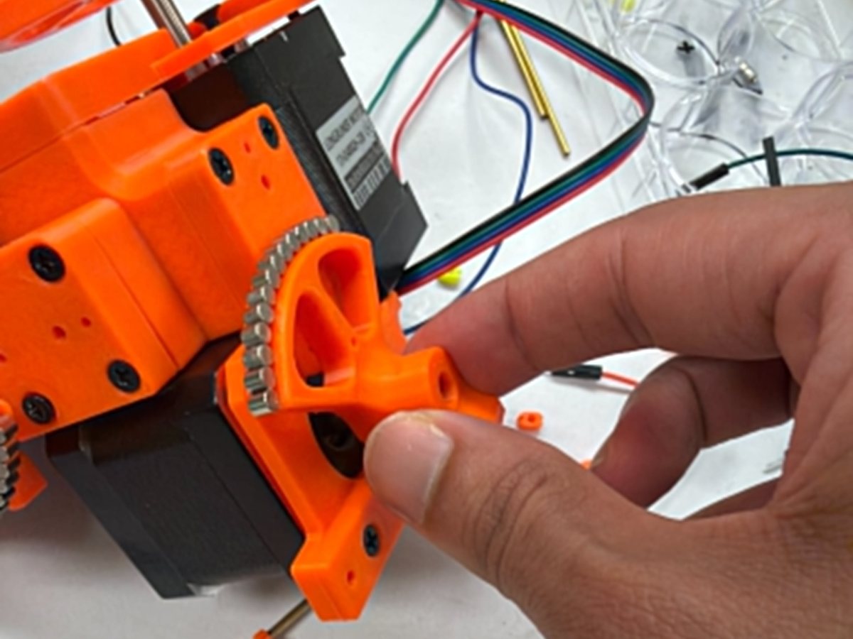
The first phase of my directed independent study was to build and evaluate an existing design rather than start from a blank sheet. The candidate was the Open Micro-Manipulator, an open source three axis motion platform by 0x23. It uses a parallel kinematic structure with miniature ball joints, off the shelf stepper motors under closed loop control, and a magnetic gearing arrangement that multiplies the resolution of low cost magnetic rotary encoders by roughly thirty times, giving commanded steps down to about 50 nm.
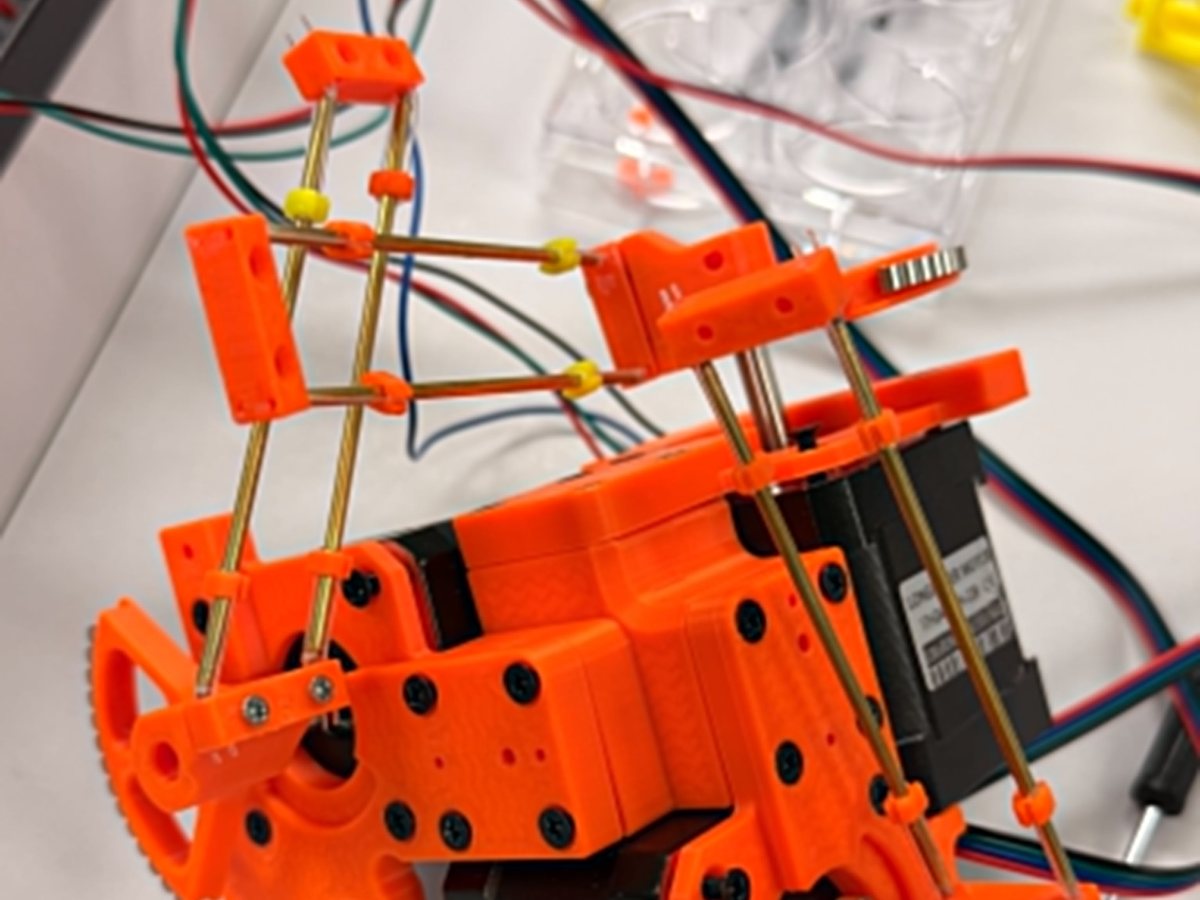
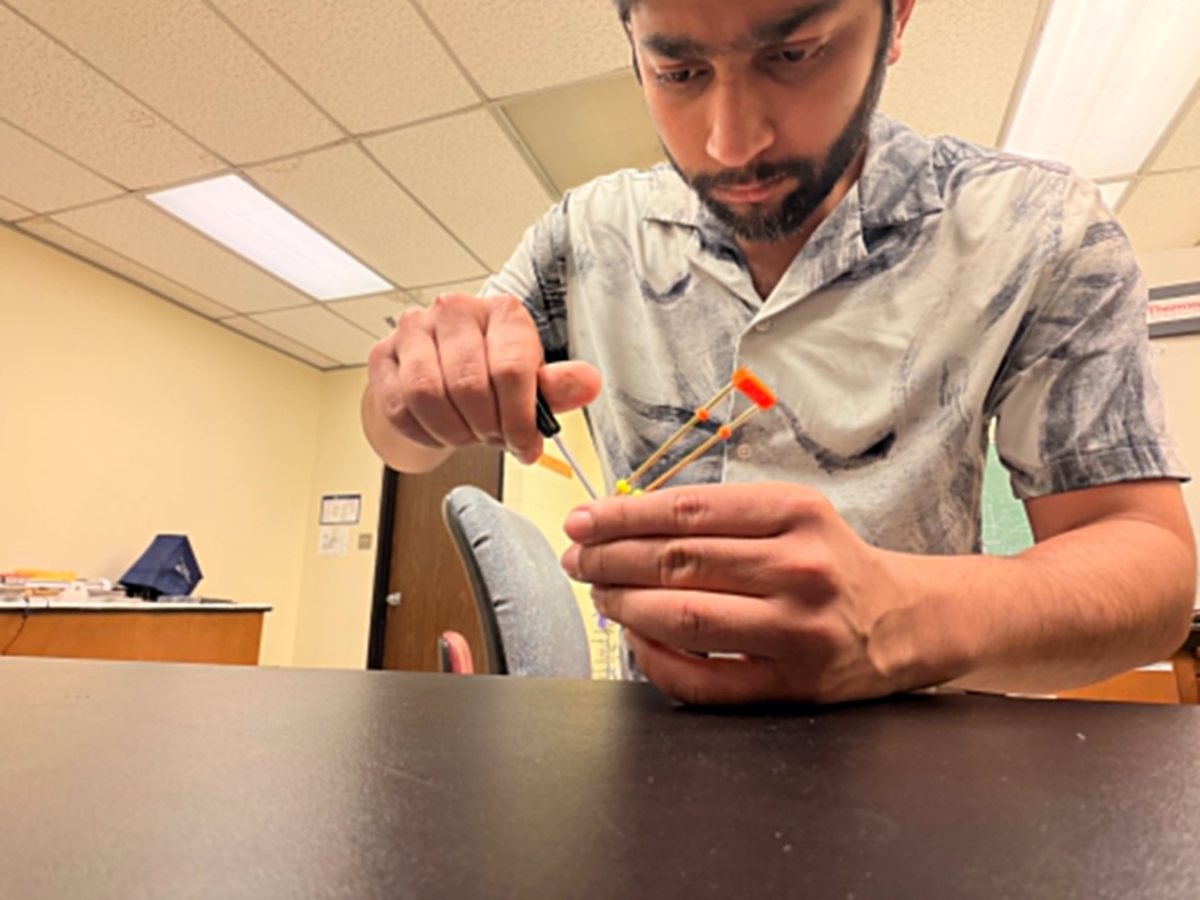
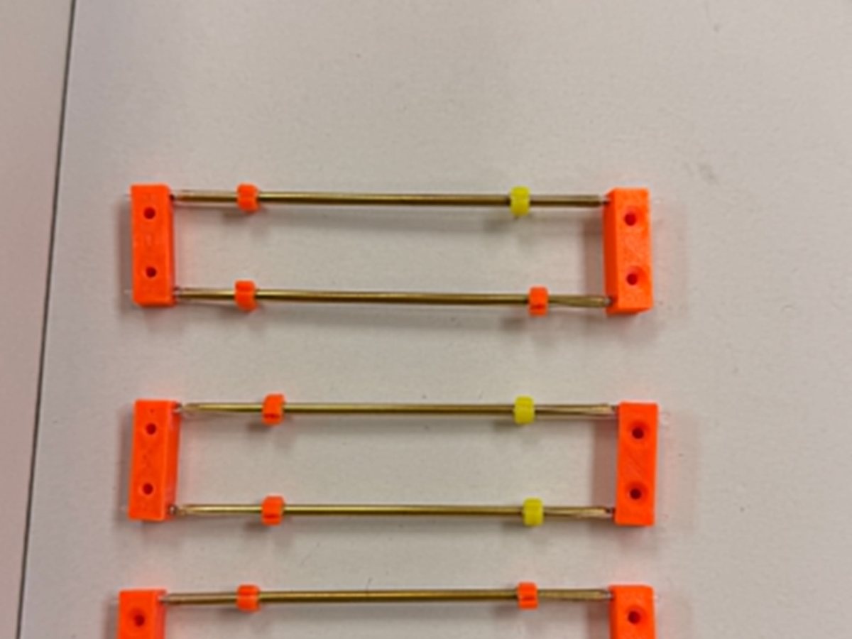
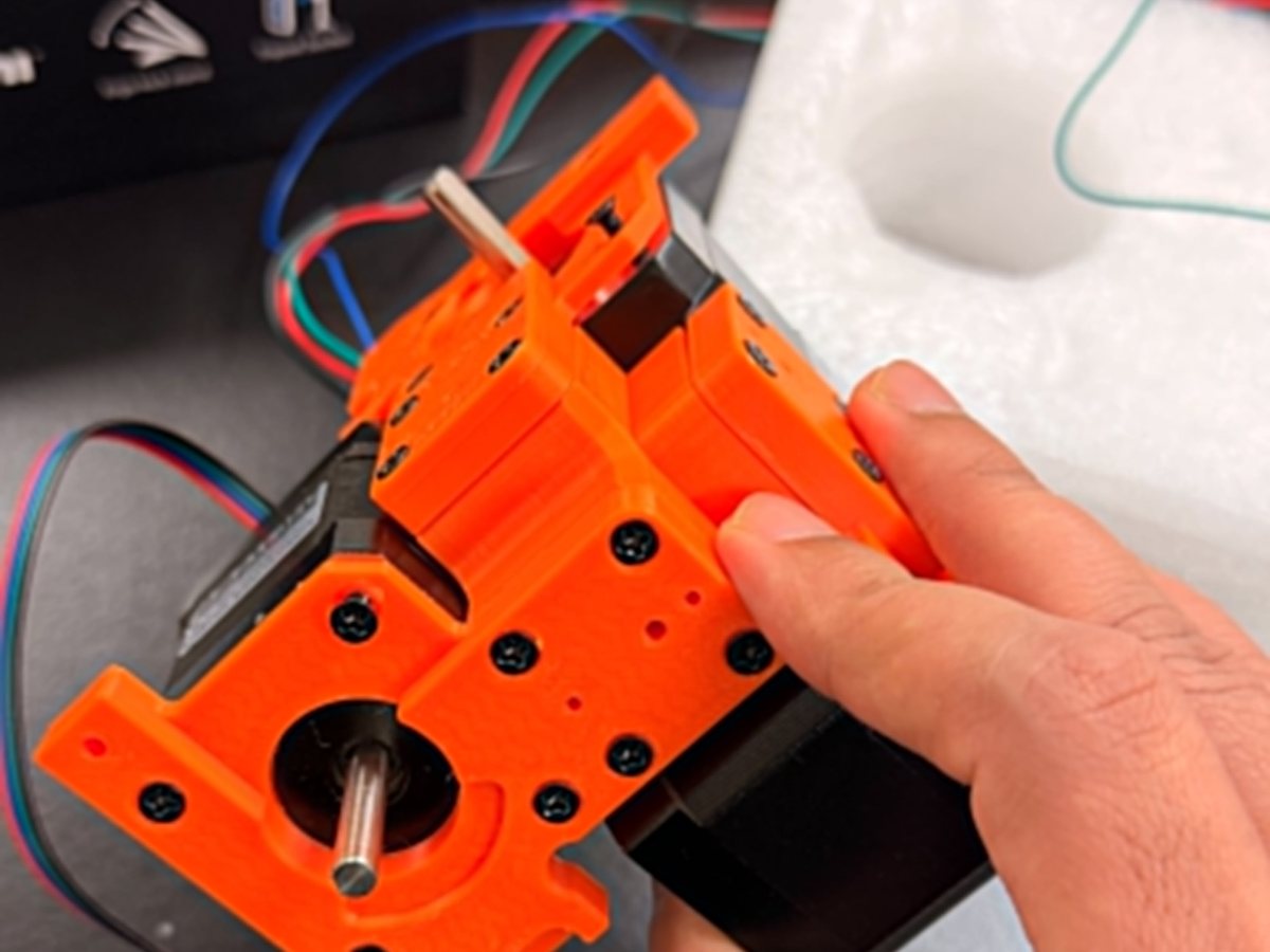
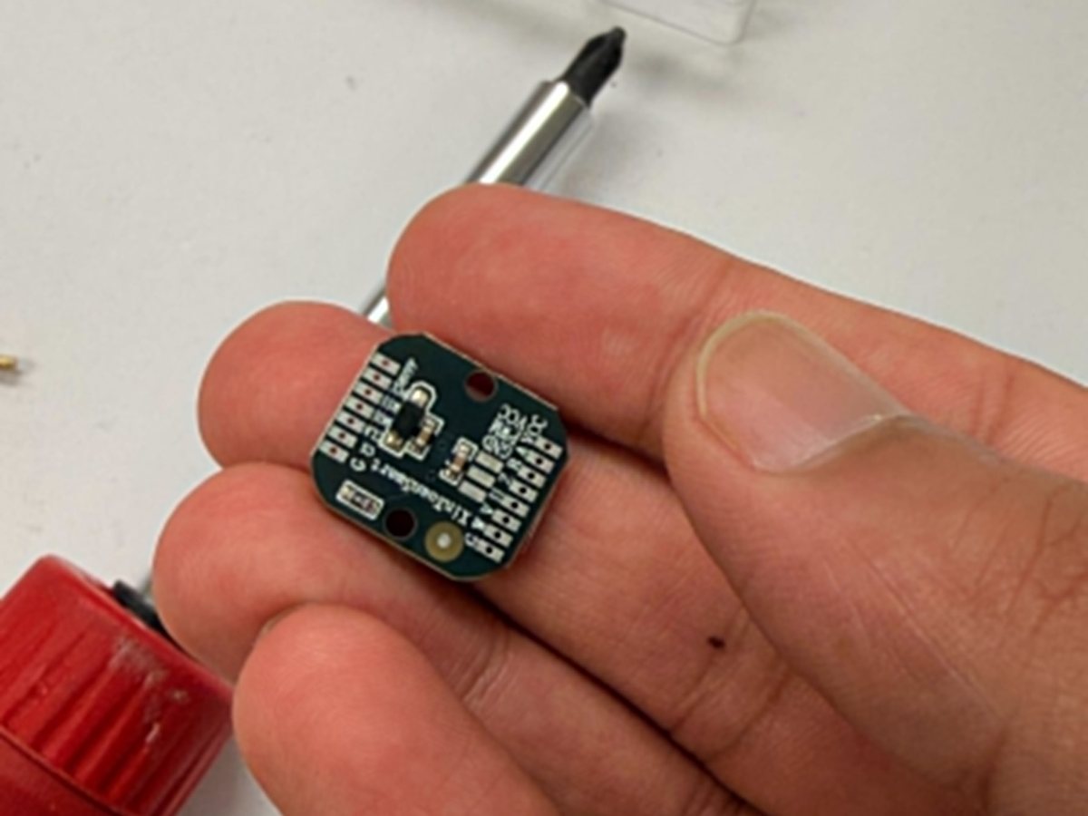
I built it. That meant printing and finishing the structural parts, assembling the parallelogram linkages from brass rod and printed blocks, fitting the ball joints, mounting the motors and magnetic gear rings, wiring the encoders, and bringing up the firmware and calibration routine. The linkage assembly in particular is fiddly work: rod length has to be consistent between the two sides of each parallelogram or the kinematics carry a built in error the controller cannot see.
The evaluation is the part that mattered. Resolution and accuracy are not the same quantity, and the gap between them turned out to be the deciding factor. The device resolves 50 nm steps because the encoder and gearing say so; whether the tip is actually where the controller believes it is depends on the mechanical chain — ball joint constraint and friction, consistency of linkage rod length, print quality at the joint seats, and thermal drift in printed structural parts. For our application the settling behaviour and repeatability were not good enough to build a laboratory instrument on, and the project's own documentation is candid that absolute accuracy is significantly worse than resolution.
Reaching that conclusion with hardware in hand rather than from a datasheet was the value of the exercise, and it shaped what came next. A three axis parallel structure with many ball joints in series accumulates error at every one of them. Constraining the problem to planar motion — which is what positioning over a plate actually requires — removes most of those joints, and that is the reasoning behind the five bar pantograph I moved on to in the second phase. Fewer joints, fewer error sources, and a geometry whose reduction ratio can be tuned by changing link length.