Five Bar Pantograph Micromanipulator
This is the mechanism I designed after evaluating a spatial parallel manipulator and finding its accuracy limited by the number of joints in the chain. A five bar parallel pantograph constrains motion to a plane, which is all that positioning over a well plate actually requires, and in doing so removes most of those error sources.
Two motors sit fixed at the base and drive four coupled links that meet at the end effector. Because neither motor rides on the moving structure, the arms carry no motor mass, so the mechanism settles faster than a stacked serial stage of comparable reach. The linkage geometry also acts as a reduction between motor rotation and tip travel: a given angular resolution at the motor produces a much finer displacement at the tip, and that ratio is set by link proportions rather than by gearing.
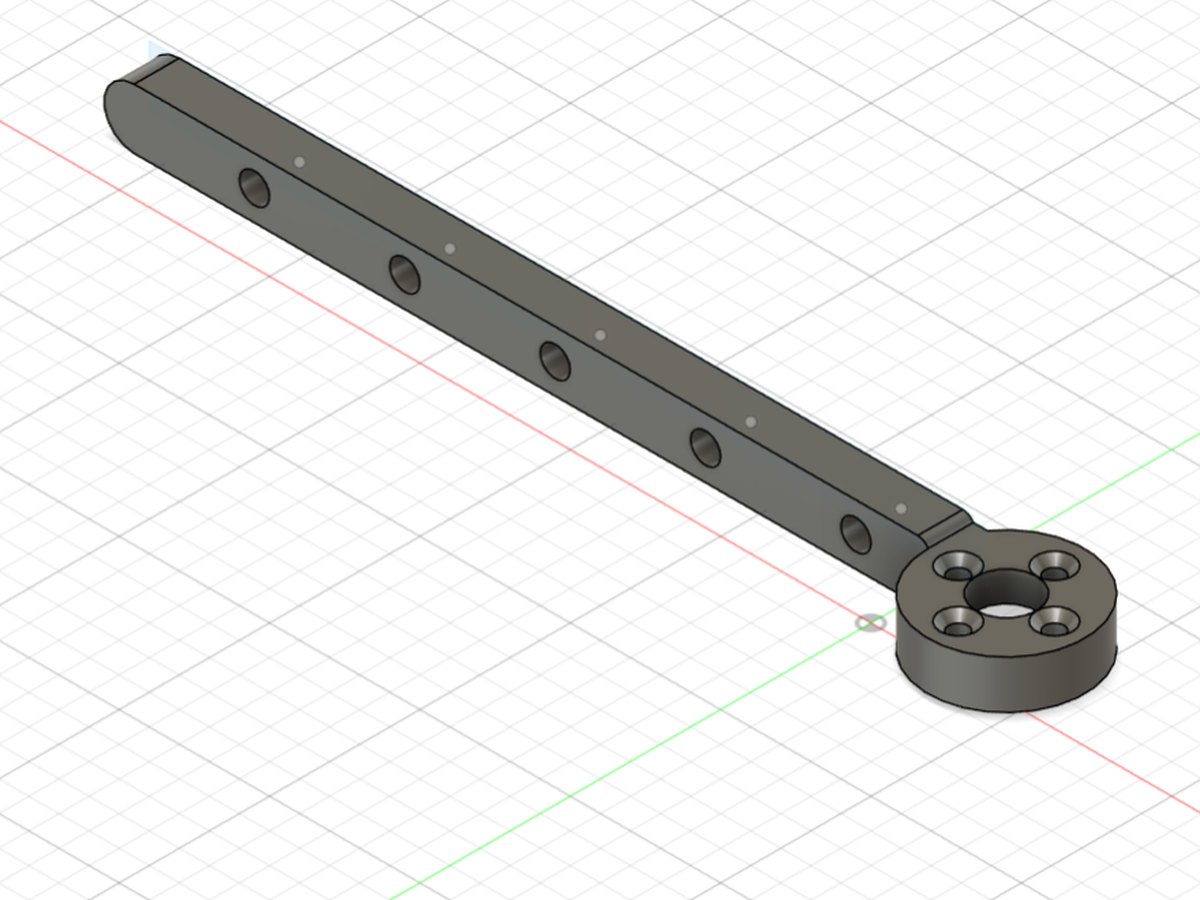
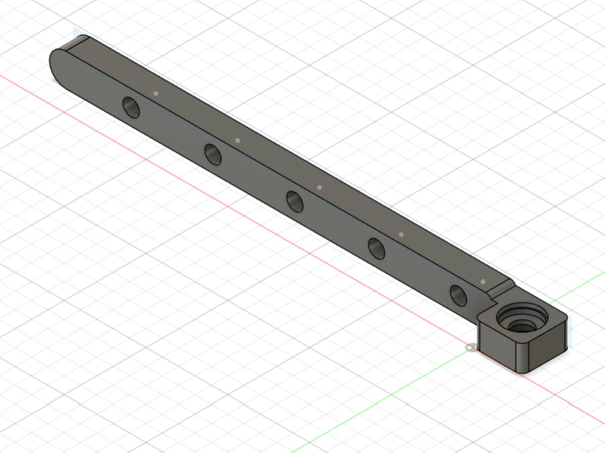
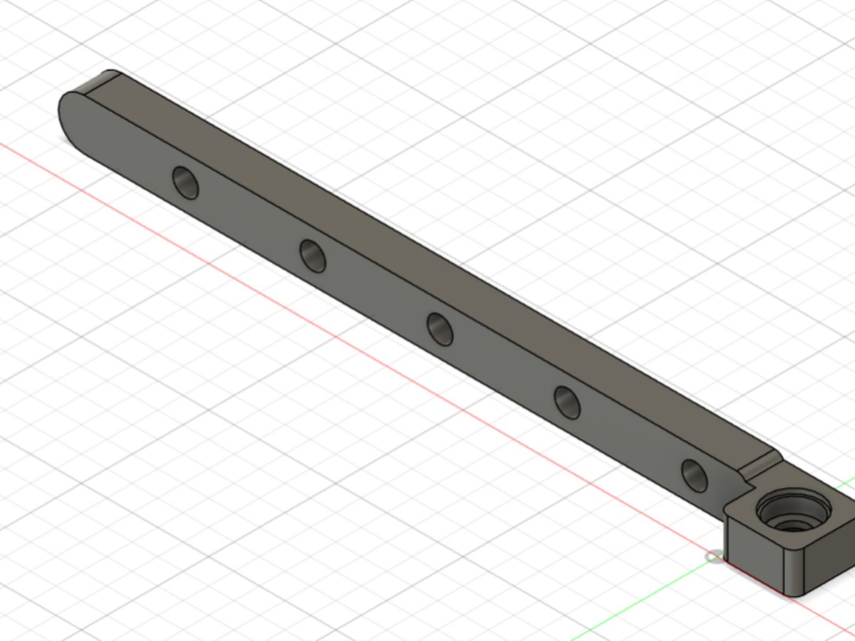
The parts above are the two link piece types. One carries a round boss with four countersunk holes on a bolt circle and a central bore, which mates to the motor output. The other carries a counterbored pivot boss for the intermediate joints. Both share the same bar section with five positions along the length.
Each of the four links is built as a pair of pieces — eight printed parts in total, one above and one below, with the pivot bosses offset toward the touching faces. This is the detail that makes the mechanism work through its whole range. A single piece link runs out of travel when the pivots collide before the workspace is swept; splitting the link and offsetting the bosses to the shared face clears the interference and allows the linkage through a full rotation. It was my advisor's suggestion and it resolved a constraint I had been designing around rather than through.
The five positions along each bar are Chicago screw locations at 25 mm spacing, cut as a counterbore from the outer face with a through hole for the remainder of the wall, so the two halves meet cleanly at their narrow sections. Effective link length can therefore be changed between tests by moving the fastener rather than reprinting a part. Since link proportions set the reduction ratio, that turns a print-and-measure cycle into a screwdriver adjustment, which matters when the useful geometry is being found experimentally.
The mechanism is designed and the parts are modelled in Fusion 360; building and characterising it is the next stage of the thesis work, alongside integrating it with the printed stage and plate fixturing already on the frame. Actuation is planned around closed loop steppers with absolute encoders on a shared CAN bus for the plane, with a voice coil handling vertical motion.